Low-E glass reflect infrared heat while letting adequate visible light through. They reduce heat gain in warm weather and heat loss in cold weather, so buildings and vehicles use less energy to stay comfortable. This makes Low-E glass ideal for architectural glazing and automotive applications. The same magnetron sputtering technology can also deposit functional coatings for optics, renewable energy, electronics, and semiconductors.
With 20+ coating lines delivered into commercial operation, we bring extensive experience in the design, installation, and commissioning of large-scale glass coating projects.
| Glass Size (W × L) | Standard sizes: 2,600 × 3,660 / 2,800 × 4,880 / 3,300 × 6,000 / 3,660 × 7,800 / 4,000 × 8,000 mm; custom lengths up to 32 m |
| Glass Thickness | Standard: 2–19 mm; up to 27 mm on request |
| Glass Gap | ≤30 mm |
| Min. Mechanical Cycle Time | 20 s |
| Maximum annual capacity | more than 20 million m² |
| Producible Glass Types | Solar Control Glass | Single-, Double- & Triple-Silver Temperable Low-E Glass | Decorative Glass | Functional Glass |
| Base Pressure | < 3.0 × 10⁻⁶ mbar |
| Single-Layer Film Uniformity | ≤1.6% |
| Rotary Cathode Target Utilization | ≥80% |
| Planar Cathode Target Utilization | ≥33% |
Vacuum Chambers
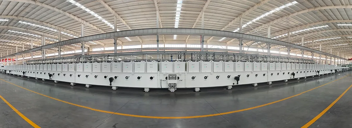
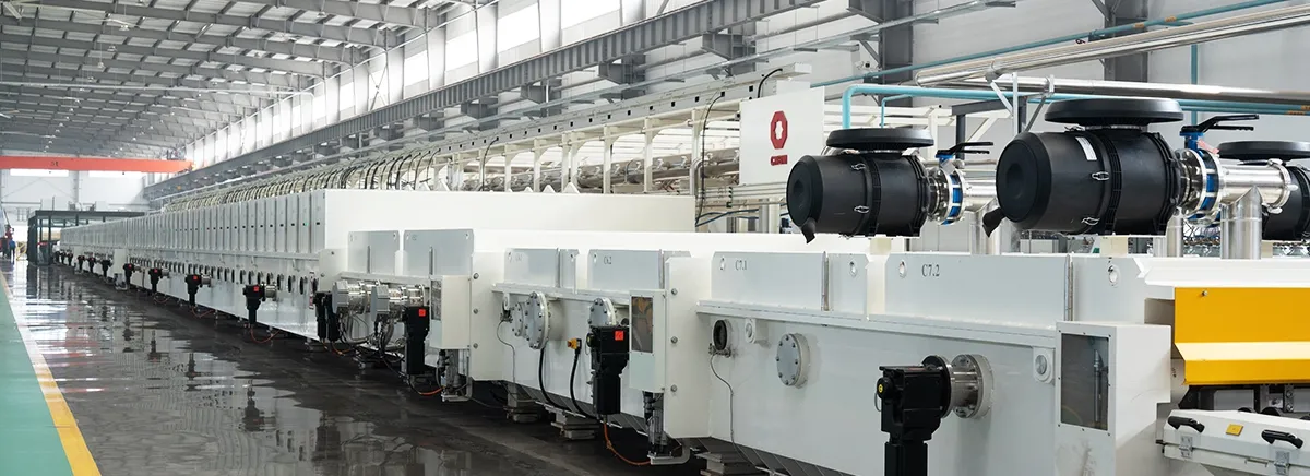
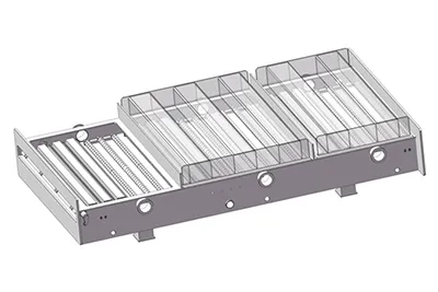
The vacuum section consists of entrance and exit lock chambers (C1/C7), buffer chambers (C2/C6), transfer chambers (C3/C5),process chambers (C4), and service valve (SV). As the glass moves through these chambers, the pressure is gradually reduced before coating and then increased back toward atmospheric pressure after the coating process.
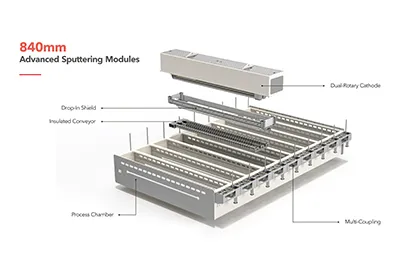
Compartment Unit
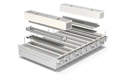
The process chamber consists of separate modules for rotary cathodes, planar cathodes, and TMPs, with spare positions reserved for future expansion. Modules can be arranged to match each line’s coating process, and spare positions can later accommodate additional cathodes or other process modules as requirements evolve.
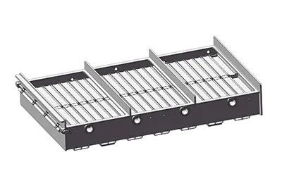
Transport System
The conveying section has conveyor rollers, servo drives, and glass position sensors to move each sheet through the vacuum chambers. The glass sheets are transported rapidly between the chambers, whereas in the coating section they are kept at a constant and controlled speed to ensure that the deposition process remains accurate over the entire surface of the glass.
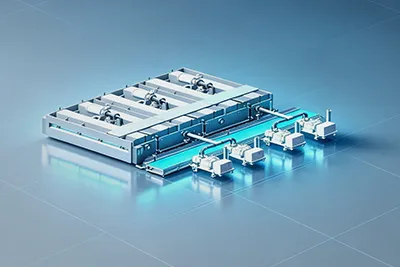
Vacuum System
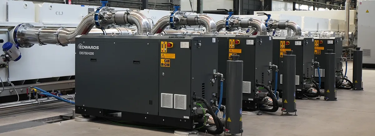
The vacuum system combines roughing pumps, high-vacuum pumps, gas-separation pumping, vacuum piping, and pressure measurement instruments. The gas isolation units, vacuum pumps, and piping maintain the required pressure in each coating chamber throughout continuous coating.
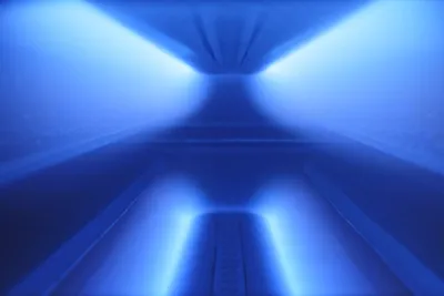
Coating System
The coating system comprises planar and rotary cathodes, process gas distribution system, and an Ex-Situ Measuring System. During sputtering, the cathodes and gas distribution system work together to deposit uniform thin films, while the ex-situ unit measures the optical performance of the coated glass.

Piping System
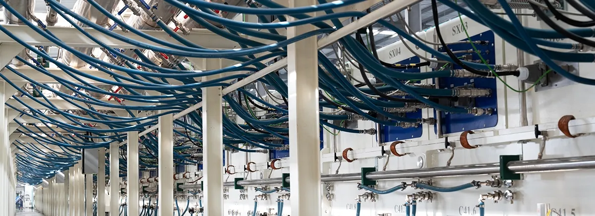
The piping system includes separate circuits for vacuum, cooling water, process gases, and compressed air. Each circuit supplies the corresponding part of the coating line with the medium it needs for operation.
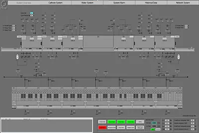
Control System
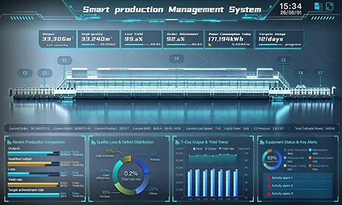
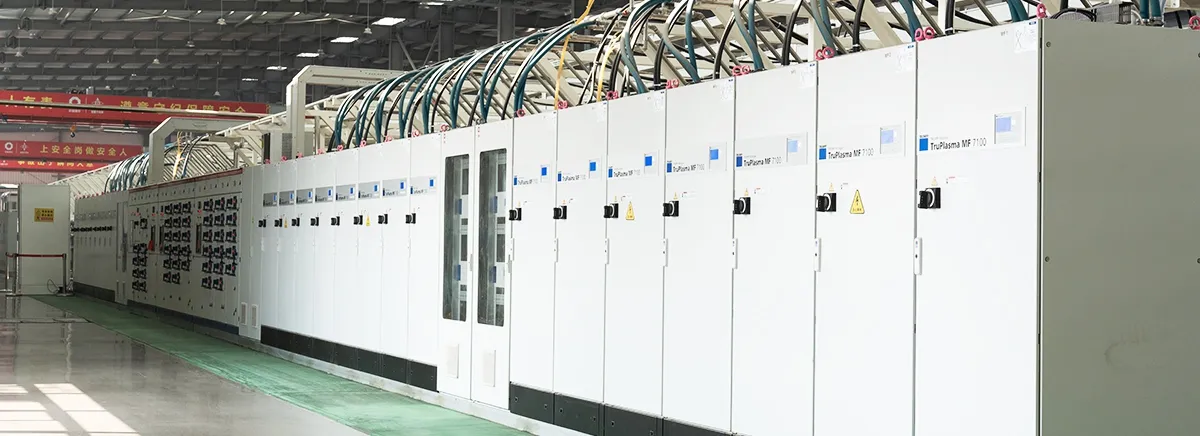
The control system consists of a high-performance CPU, an industrial UPS, Siemens WinCC software, and a HMI interface. Operators can set process parameters, check the status of the coating line, control automatic sequences, and view safety interlock or fault information directly from the HMI.